Whether you were aware of them or not, Hall effect sensors are everywhere. Any time you see a motor on an appliance with any kind of RPM feedback or speed signal, there’s a Hall sensor on that motor. As with any ubiquitous appliance technology, it’s important for us techs to know how they work. A deeper understanding of the technology means a deeper understanding of how to troubleshoot it.
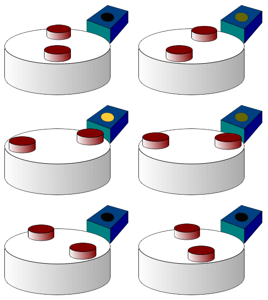
So: what is a Hall sensor, and how does it work? These are semiconductor devices, so as with most electronics, it’s not important to get too far into the weeds. We just want a functional understanding of them as far as it affects our troubleshooting. To that end, here’s a little gif to show you a Hall sensor in action:

Those red discs are permanent magnets — something similar to the kind you might use to stick something to your refrigerator. The blue box is the actual Hall sensor. Notice how, every time the spinning white disc (assume that’s the rotor of a motor) takes a magnet past the Hall sensor, the sensor lights up. This is all Hall sensors do. They detect the proximity of a magnet. It’s that simple.
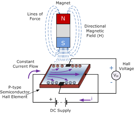
How doe they do this? By using an electromagnetic principle known as the Hall effect — hence whey they are properly called Hall effect sensors. The Hall effect states that, if you have a current flowing through a conductor, and you then apply a magnetic field to that conductor, it will induce a voltage difference across that conductor perpendicular to the current flow. This induced voltage difference is often called the Hall voltage.
Here’s an image demonstrating the Hall effect in action in a Hall sensor.

Again, not important that you completely wrap your head around everything that’s going on inside one of these sensors. What’s important is that you understand what inputs a Hall sensor needs and what it outputs.
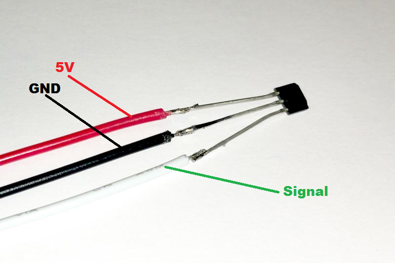
Below is what a Hall sensor looks like physically. Note that it has three terminals, and in this picture, each terminal is labeled with what that terminal carries.

Super simple — you’ve just got a 5 VDC power supply, a DC ground, and then the signal, which is just that induced DC voltage — the Hall voltage — from the magnet that we talked about before. The 5 VDC and the DC ground are there to produce the constant current through the sensor, across which the Hall voltage is induced.
All three of these wires would connect back to a control board. This board supplies the DC voltage and ground, and it receives the sensor’s signal as an input. The logic on the board then interprets that signal to make calculations about whether the motor is running and how quickly it is turning.
So now that you know how they work, how do you test a Hall sensor? It’s actually very simple, and you might have guessed at this point. All you need to do is manually spin the motor that the sensor is attached to while you have your voltmeter measuring the signal line wrt DC ground. If you see some fluctuating voltage appear while the motor is spinning, you know that the sensor is doing its job.
And that’s all there is to it! Very simple, but very useful and versatile devices. We see them all over the place, and now you know what’s going on inside that little black semiconductor.
Want to really understand the technologies present in all appliances and learn how to apply that knowledge to your appliance troubleshooting for maximum profits? Click below to check out our online Core Appliance Repair Training course right here at the Master Samurai Tech Academy.